
F Series Parallel Shaft Gearmotor – Helical Gear Reducer
Extra-slim parallel shaft gearmotor for space-limited applications. 0.18-200kW power, torque to 18000Nm, ratios 3.81-270.16. Perfect for conveyors & material handling.
Product Introduction
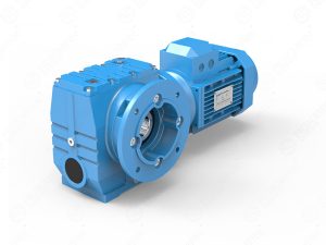
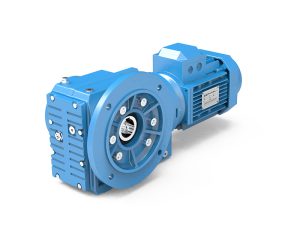
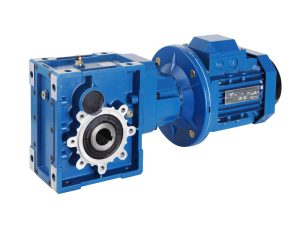
The F Series parallel shaft gearmotor features hardened helical gears in a compact, extra-slim parallel shaft configuration. This helical gear reducer series provides power transmission from 0.18 kW to 200 kW with maximum torque capacity reaching 18,000 N·m. The parallel shaft design offers ten frame sizes (F38 through F158) across multiple mounting configurations, addressing diverse installation requirements. The series is modular in design with cast iron housing construction, serving as the perfect solution when space is limited.
Core Design Elements
Cast Iron Housing Construction
The gearmotor housing utilizes cast iron material, providing structural support for the parallel shaft helical gear arrangement. The housing design accommodates the parallel shaft configuration where input and output shafts are positioned parallel to each other.
Hardened Helical Gear Technology
The transmission system employs hardened helical gears arranged in parallel shaft configuration. The helical gear profile enables smooth power transmission with the parallel shaft orientation characteristic of the F Series design. Multi-stage gear units featuring 2-stage or 3-stage arrangements enable low output speed applications.
Modular System Design
Eleven Series Configurations
The F Series encompasses eleven distinct model ranges addressing various output shaft and mounting requirements:
F Series (Standard): Foot-mounted configuration with solid shaft output. Models from F38 through F158 provide output shaft diameters from Ø25mm to Ø120mm solid shaft.
FAB Series: Foot-mounted design featuring hollow shaft output. This configuration offers hollow output shaft options across the frame size range.
FA Series: Equipped with keyed hollow shaft output, providing mechanical connection through keyway design.
FF Series: B5 flange-mounted configuration with solid shaft output, enabling direct flange attachment to equipment following B5 specifications.
FAF Series: B5 flange-mounted design incorporating hollow shaft output, combining B5 flange mounting with hollow shaft configuration.
FAZ Series: B14 flange-mounted configuration with hollow shaft output, accommodating B14 standard flange dimensions.
FAT Series: Features hollow shaft output with integrated torque arm for shaft-mounted installations.
FH, FHB, FHF, FHZ Series: Hollow shaft output configurations equipped with shrink disk connection system for secure shaft mounting without keyways.
FV, FVB, FVF, FVZ Series: Hollow shaft output with splined hollow shaft design, providing alternative connection method for output shaft attachment.
F(FA, FF, FAF, FAB, FAZ)S Series: Solid shaft input variants of the respective series, accepting power input through solid input shaft instead of direct motor mounting.
Multi-Stage Reduction Options
The series provides 2-stage or 3-stage gear unit configurations for applications requiring low output speed. Multi-stage arrangements enable higher reduction ratios within the parallel shaft housing design, with ratio ranges from 3.81 to 270.16 across the complete model range.
Motor Integration Options
Electric Motor Configurations
The F Series accommodates direct motor mounting through equipped electric motor configurations. Standard input arrangements include IEC-normalized motor flange connections, enabling compatibility with various motor types.
Applicable Motor Types
The design supports integration with multiple motor categories:
Single Phase AC Motor: Compatible with single-phase power supply applications.
Three Phase AC Motor: Accommodates standard three-phase industrial motors across the power range.
Brake Motors: Accepts motors equipped with electromagnetic braking systems.
Inverter Motors: Compatible with variable frequency drive (VFD) controlled motors for speed regulation applications.
Multi-Speed Motors: Supports motors featuring multiple speed winding configurations.
Explosion-Proof Motors: Accepts certified explosion-proof motors for hazardous environment installations.
Roller Motors: Compatible with specialized roller motor configurations.
Input Configuration Flexibility
Beyond direct motor mounting, the series offers solid shaft input options through the “S” series variants (FS, FAS, FFS, FAFS, FABS, FAZS). These configurations accept power input via solid input shaft with keyway, enabling connection to separate drive sources or non-standard motors.
Output Shaft Configurations
Solid Shaft Output
Standard F Series and FF Series models feature solid shaft output with keyed connection. Output shaft diameters range from Ø25mm through Ø120mm depending on model size, providing direct shaft coupling capability.
Hollow Shaft Output Options
Multiple hollow shaft configurations address different mounting and connection requirements:
Keyed Hollow Shaft (FA Series): Hollow output shaft incorporates keyway for traditional keyed connection to driven equipment shafts.
Shrink Disk Connection (FH, FHB, FHF, FHZ Series): Hollow shaft utilizes shrink disk mounting system, providing keyless connection through friction fit. This method enables precise centering and facilitates assembly/disassembly procedures.
Splined Hollow Shaft (FV, FVB, FVF, FVZ Series): Output shaft features internal splines, enabling splined shaft connection without keyway requirements.
Torque Arm Configuration (FAT Series): Hollow shaft output designed for shaft-mounted installations, incorporating torque arm assembly to absorb reaction forces during operation.
Technical Specifications
Complete Model Range Parameters
| Model | Solid Shaft Output | Hollow Shaft Output | Input Shaft | Power (kW) | Ratio Range | Max Torque (Nm) |
|---|---|---|---|---|---|---|
| F38 | Ø25mm | Ø30mm | Ø16mm | 0.18-3.0 | 3.81-128.51 | 200 |
| F48 | Ø30mm | Ø35mm | Ø16mm | 0.18-3.0 | 5.06-189.39 | 400 |
| F58 | Ø35mm | Ø40mm | Ø19mm | 0.18-5.5 | 5.18-199.70 | 600 |
| F68 | Ø40mm | Ø40mm | Ø19mm | 0.18-5.5 | 4.21-228.99 | 820 |
| F78 | Ø50mm | Ø50mm | Ø24mm | 0.37-11 | 4.30-281.71 | 1,500 |
| F88 | Ø60mm | Ø60mm | Ø28mm | 0.75-22 | 4.20-271.92 | 3,000 |
| F98 | Ø70mm | Ø70mm | Ø38mm | 1.1-30 | 4.68-276.64 | 4,300 |
| F108 | Ø90mm | Ø90mm | Ø42mm | 2.2-45 | 6.20-255.25 | 7,840 |
| F128 | Ø110mm | Ø100mm | Ø55mm | 7.5-90 | 4.63-172.33 | 12,000 |
| F158 | Ø120mm | Ø120mm | Ø70mm | 11-200 | 12.07-270.16 | 18,000 |
Product Features
The F Series parallel shaft gearmotor incorporates the following specified features:
1. Modular Design, Compact Structure. Extra-Slim Parallel Shaft Helical Gearmotors are the Perfect Solution When Space is Limited: The modular architecture enables various configurations from standardized components. The extra-slim parallel shaft design provides space-efficient installation where compact dimensions are required. This configuration proves ideal for applications with restricted mounting space.
2. F Series Parallel Shaft Helical Gearmotors are Typically Used in Conveyors and Materials Processing Applications: The design characteristics suit conveyor drive systems and material processing equipment. The parallel shaft configuration accommodates the mounting requirements common in conveyor and material handling installations.
3. Multi-Stage (2 or 3 Stages) Gear Units for Low Output Speed: Two-stage or three-stage configurations enable low output speed requirements through increased reduction ratios. Multi-stage arrangements achieve greater speed reduction within the parallel shaft housing design.
4. Hollow Output Shaft with Keyed Connection, Shrink Disk, Splined Hollow Shaft, or Torque Arm: Multiple hollow shaft configurations are available including keyed connection (FA Series), shrink disk (FH Series), splined hollow shaft (FV Series), and torque arm variants (FAT Series), addressing diverse mounting and connection requirements.
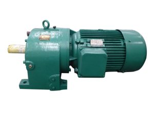
5. Can be Combined with Other Types of Gearboxes (Such as R Series, UDL Series): The series can be combined with R Series coaxial helical gearboxes and UDL Series stepless variators for expanded drive configuration possibilities. Combination options extend ratio ranges and enable specific output orientations.
6. Optional Mounting Options (Foot-Mounted, Flange-Mounted, Shaft-Mounted): Three mounting methods accommodate different installation requirements. Foot-mounted (F, FAB, FA Series) provides standard base mounting. Flange-mounted (FF, FAF, FAZ Series) enables direct equipment attachment via B5 or B14 flanges. Shaft-mounted (FAT Series) allows hanging installation on driven shafts with torque arm support.
Installation Methods
Foot-Mounted Configuration
Foot-mounted models (F Series, FAB Series, FA Series) feature mounting feet for installation on horizontal surfaces or equipment bases. This configuration provides stable support and accommodates various foundation designs.
B5 Flange-Mounted
B5 flange-mounted variants (FF Series, FAF Series) incorporate B5 standard flange dimensions for direct attachment to equipment flanges or motor brackets. This mounting method eliminates separate foot-mounted base requirements.
B14 Flange-Mounted
B14 flange-mounted configuration (FAZ Series) utilizes B14 standard flange specifications, providing alternative flange mounting option for equipment with B14 flange interfaces.
Shaft-Mounted
Shaft-mounted installation (FAT Series and torque arm configurations) enables direct mounting onto driven equipment shafts. The torque arm assembly absorbs reaction forces, securing the gearmotor position during operation without separate mounting base.
System Integration Capability
Combination with Other Gearbox Types
The F Series design enables combination with additional gearbox types to expand application possibilities:
F + R Series Combination: Connecting F Series parallel shaft units with R Series coaxial helical gearboxes creates combined drive configurations. This arrangement can achieve extended ratio ranges or specific shaft orientation requirements.
F + UDL Series Combination: Integration with UDL Series stepless variators enables variable speed control capability. The combination provides adjustable output speed while maintaining the parallel shaft configuration of the F Series.
These combination options utilize standard interface connections between gearbox types, facilitating system assembly for specialized drive requirements.
Conveyor and Material Processing Applications
The F Series parallel shaft helical gearmotor serves as a typical solution for conveyors and materials processing applications. The extra-slim design accommodates the space constraints common in conveyor installations where mounting depth is limited. The parallel shaft configuration aligns with conveyor drive mounting requirements, simplifying integration into conveyor frames and material handling equipment.
Multiple hollow shaft output options suit various conveyor drum shaft mounting methods. Keyed hollow shaft (FA Series) provides traditional keyway connection. Shrink disk mounting (FH Series) enables keyless installation on conveyor drums. Splined hollow shaft (FV Series) accommodates splined drum shaft designs. Torque arm configuration (FAT Series) supports hanging shaft-mounted installations directly on conveyor rollers.
The modular design with optional mounting arrangements (foot, flange, shaft-mounted) addresses diverse conveyor equipment configurations. Multi-stage gear units deliver the low output speeds required for heavy-duty conveyor applications, while the wide ratio range from 3.81 to 270.16 enables precise speed matching to material transport requirements.
Lubrication and Cooling Systems
Oil-Bath and Splash Lubrication
The gearmotor employs oil-bath and splash lubrication methodology. Gear rotation distributes lubricant throughout the gear chamber, providing continuous lubrication to all meshing surfaces and bearing locations. This passive lubrication system operates without external pumps or circulation equipment.
Natural Cooling Design
Heat dissipation occurs through natural cooling from the cast iron housing surfaces. The housing design facilitates heat transfer from internal components to the external environment through natural convection and radiation, maintaining operational temperatures without forced cooling systems.
Quick Specifications Reference
| Parameter | Specification |
|---|---|
| Power Range | 0.18 ~ 200 kW |
| Max Torque | Up to 18,000 N·m |
| Ratio Range | 3.81 ~ 270.16 |
| Housing Material | Cast Iron |
| Gear Type | Hardened Helical |
| Drive Configuration | Parallel Shaft |
| Output Options | Solid Shaft, Hollow Shaft (keyed, shrink disk, splined, torque arm) |
| Input Options | Direct Motor Mount (IEC flange), Solid Shaft Input |
| Motor Compatibility | Single/Three-phase, Brake, Inverter, Multi-speed, Explosion-proof, Roller |
| Mounting Types | Foot-mounted, B5 Flange, B14 Flange, Shaft-mounted |
| Stages Available | 2-stage, 3-stage |
| Lubrication | Oil-bath & Splash |
| Cooling | Natural Cooling |
| Combination Options | Compatible with R Series, UDL Series |
| Typical Applications | Conveyors, Materials Processing Equipment |
| Key Features | Extra-slim design, Modular construction, Multiple mounting options |
For detailed selection guidance or custom configuration requirements, please consult our application engineering team.
Reviews
There are no reviews yet.