


ZJY Shaft Mounted Gearbox – Industrial Helical Gear Reducer
Heavy-duty helical gear reducer for conveyor systems. Hardened gears with 6-class accuracy, 750-14720Nm torque range. Perfect for mining, material handling & elevator applications.
Product Introduction
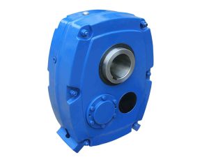
The ZJY Series represents a professional-grade industrial helical gear reducer engineered for demanding conveyor applications across mining, material handling, and bulk transport sectors. This shaft mounted gearbox combines robust cast iron construction with precision-hardened helical gearing, delivering exceptional torque capacity from 750 N·m to 14,720 N·m across seven model sizes. Designed for continuous heavy-duty operation, these reducers provide reliable power transmission in belt conveyors, scraper conveyors, and bucket elevator installations where operational uptime is critical.
Engineering Excellence
Robust Cast Iron Housing
The gearbox housing utilizes high-grade cast iron construction, selected for its superior structural rigidity and excellent vibration damping characteristics. This material choice provides the dimensional stability necessary to maintain precise gear alignment under sustained heavy loads typical of industrial conveyor operations. Cast iron’s natural vibration absorption properties reduce noise transmission to mounting structures, creating a quieter operational environment while extending component service life through reduced fatigue stress.
The housing design incorporates optimized wall thickness distribution, balancing weight considerations with structural strength requirements. Internal ribbing patterns reinforce critical load-bearing areas while facilitating efficient lubricant circulation throughout the gear chamber. Precision-machined mounting surfaces ensure accurate assembly and reliable sealing performance over extended service intervals.
Precision Hardened Helical Gears
Transmission components feature hardened helical gears manufactured through a comprehensive heat treatment process including carburizing, quenching, and precision grinding operations. This multi-stage processing creates a hard, wear-resistant surface layer while maintaining a tough, shock-resistant core structure. The gradient hardness profile optimizes load distribution across gear teeth, significantly extending operational life under continuous duty cycles.
Helical gear geometry provides gradual tooth engagement, resulting in smooth power delivery with minimal vibration and noise generation. The angled tooth configuration distributes loads across multiple teeth simultaneously, increasing load capacity by approximately 40% compared to equivalent spur gear designs. Achieving 6-class gear accuracy ensures precise meshing characteristics, minimizing friction losses and maintaining transmission efficiency above 95% throughout the operational envelope.
The grinding process applied to heat-treated gear teeth removes heat treatment distortion, restoring geometric precision essential for quiet, efficient operation. This final machining step creates the surface finish quality necessary for proper lubricant film formation, reducing wear rates and extending maintenance intervals in demanding industrial environments.
High-Quality Alloy Steel Shafts
Input and output shafts are manufactured from high-quality alloy steel, selected for superior torsional strength and fatigue resistance properties. The alloy composition provides the mechanical characteristics necessary to withstand repeated loading cycles without deformation or crack propagation. Precision machining ensures accurate dimensional tolerances on bearing seats, keyways, and mounting surfaces, facilitating proper component assembly and load transfer.
Output shafts feature keyed hollow bore configurations, enabling direct mounting onto conveyor drum shafts without intermediate couplings or adapter components. This design simplifies installation procedures while eliminating potential alignment issues associated with coupled drive arrangements. Input shafts incorporate standard keyed solid configurations, accommodating various motor mounting arrangements and power transmission requirements.
Configuration & Installation
Bi-Directional Rotation Capability
The reducer supports both clockwise and counterclockwise output shaft rotation, providing installation flexibility for diverse conveyor layouts. Standard configurations permit free bi-directional operation, suitable for reversible conveyor applications such as shuttle systems or load/unload stations. When equipped with optional backstop devices, the unit operates in unidirectional mode, preventing backdriving in inclined conveyor installations where gravity could reverse belt travel during power interruptions.
This rotational flexibility eliminates the need to stock separate clockwise and counterclockwise models, simplifying spare parts inventory management while accelerating emergency replacement procedures. Engineers can specify rotation direction during installation setup, adapting the same reducer model to various system requirements without custom manufacturing delays.
Hanging Shaft Mounted Installation
The primary mounting method suspends the reducer directly onto the conveyor drum shaft using an integrated torque arm assembly. This hanging configuration eliminates separate mounting bases, couplings, and alignment procedures that complicate traditional drive installations. The torque arm effectively absorbs reaction forces generated during power transmission, protecting the conveyor frame structure from torsional stress while accommodating thermal expansion without constraint.
Hanging installation significantly reduces installation time compared to base-mounted alternatives. Maintenance personnel can remove and replace complete drive assemblies without disturbing conveyor alignment or belt tracking settings, minimizing system downtime during planned maintenance or emergency repairs. The self-contained design proves particularly valuable in retrofit applications where existing conveyor structures may not accommodate traditional mounting arrangements.
Pulley-Equipped Configurations
Units equipped with integrated pulleys enable direct belt drive from electric motors without separate V-belt sheave installations. This configuration simplifies the drive train, reducing component count while improving power transmission efficiency. Pulley sizing options accommodate various motor speeds and belt velocities, providing engineers with flexibility during system design and motor selection phases.
The integrated pulley design maintains proper alignment between motor and reducer input shafts, eliminating the belt tracking issues common with separately mounted pulley arrangements. Reduced vibration from improved alignment extends belt service life while decreasing maintenance requirements for tension adjustment and pulley realignment procedures.
Technical Specifications
Model Range & Capacity
Seven standard models from ZJY106 through ZJY300 provide comprehensive torque coverage for light-duty through heavy-duty industrial conveyor applications:
| Model | Output Bore | Input Power | Max Torque | Available Ratios | Weight |
|---|---|---|---|---|---|
| ZJY106 | 45mm | 2.3-12 kW | 750 N·m | 10, 11.2, 12.5, 14, 16, 18, 20, 22.4, 25 | 27 kg |
| ZJY125 | 55mm | 3.8-19 kW | 1,250 N·m | 10, 11.2, 12.5, 14, 16, 18, 20, 22.4, 25 | 40 kg |
| ZJY150 | 60mm | 7.1-33 kW | 2,120 N·m | 10, 11.2, 12.5, 14, 16, 18, 20, 22.4, 25 | 67 kg |
| ZJY180 | 70mm | 11-56 kW | 3,550 N·m | 10, 11.2, 12.5, 14, 16, 18, 20, 22.4, 25 | 110 kg |
| ZJY212 | 85mm | 19-92 kW | 6,000 N·m | 10, 11.2, 12.5, 14, 16, 18, 20, 22.4, 25 | 173 kg |
| ZJY250 | 100mm | 32-157 kW | 10,000 N·m | 10, 11.2, 12.5, 14, 16, 18, 20, 22.4, 25 | 250 kg |
| ZJY300 | 120mm | 46-225 kW | 14,720 N·m | 10, 11.2, 12.5, 14, 16, 18, 20, 22.4, 25 | 380 kg |
Ratio Selection Flexibility
Nine standard reduction ratios (10, 11.2, 12.5, 14, 16, 18, 20, 22.4, 25) provide precise speed matching for diverse conveyor applications. This comprehensive ratio range enables engineers to optimize belt velocity while maintaining motor operation within efficient speed bands. Fine ratio increments facilitate accurate matching to material transport requirements without compromising motor efficiency or requiring variable frequency drives for speed adjustment.
The ratio selection accommodates both high-speed, light-load conveyors typical of baggage handling systems and low-speed, heavy-load applications common in mining and aggregate transport. Engineers can calculate optimal combinations of motor speed, reducer ratio, and drum diameter to achieve target belt velocities while maximizing system efficiency and minimizing energy consumption.
Industrial Applications
Belt Conveyor Systems
Belt conveyors in mining operations, quarries, and bulk material processing facilities rely on ZJY reducers for primary drive power. The robust construction withstands continuous operation under fluctuating loads where material surges and impact conditions occur regularly. Hardened helical gears maintain smooth operation despite load variations, preventing belt slippage and ensuring consistent material flow rates critical for downstream process control.
The hanging shaft mounted design proves particularly advantageous in long conveyor installations where multiple drive points distribute total power requirements. Individual reducers can be added or removed without affecting adjacent drive stations, simplifying capacity modifications as production demands evolve. Standardized output bore dimensions across model sizes facilitate drum shaft standardization, reducing spare parts inventory complexity.
Scraper Conveyor Applications
Coal mines and industrial facilities utilize scraper conveyors (also known as chain conveyors or pan conveyors) for material transport in confined spaces. The ZJY Series provides the high starting torque necessary to overcome static friction in heavily loaded chains. Bi-directional rotation capability suits reversible scraper systems that alternate material flow direction based on operational requirements.
Cast iron housing construction resists the abrasive dust environment typical of scraper conveyor installations. The sealed housing design protects internal components from coal dust, mineral particles, and other contaminants that could accelerate wear or cause premature failure. Oil-bath lubrication maintains proper gear protection despite external contamination exposure, extending service intervals between maintenance procedures.
Bucket Elevator Drives
Grain handling facilities, cement plants, and chemical processing operations employ bucket elevators for vertical material transport. The ZJY reducer’s high torque capacity suits the demanding starting loads imposed by elevators filled with material during startup sequences. Optional backstop devices prevent reverse rotation during power interruptions, eliminating dangerous material spillage and protecting elevator structures from reverse-direction impact loads.
Precise 6-class gear accuracy ensures smooth, vibration-free operation critical for bucket elevator applications where excessive vibration could dislodge material from buckets or cause premature chain fatigue. The consistent speed control provided by precision gearing maintains optimal bucket spacing for efficient material discharge, maximizing throughput while minimizing spillage at discharge points.
Lubrication & Maintenance
Oil-Bath Splash Lubrication System
The reducer employs proven oil-bath and splash lubrication methodology where rotating gears submerge partially in the oil reservoir, distributing lubricant across all meshing surfaces through centrifugal action and splash patterns. This passive system operates without pumps, filters, or control circuits, maximizing reliability while eliminating potential failure points associated with forced lubrication systems.
Internal oil circulation patterns developed during operation ensure complete coverage of bearings, gear teeth, and seal areas. The oil reservoir capacity provides sufficient thermal mass to absorb operational heat, stabilizing oil temperature during normal duty cycles. Simple sight glass indicators enable quick visual oil level verification during routine inspections, with dipstick markings confirming proper fill quantities during maintenance procedures.
Lubricant selection follows standard industrial gear oil specifications, with viscosity grades chosen based on ambient temperature ranges and operational duty cycles. Mineral-based oils suit most applications, while synthetic lubricants extend service intervals in severe duty or extreme temperature environments. Initial oil fill typically provides 4,000-6,000 operating hours before scheduled changes, with actual intervals adjusted based on oil analysis results and visual condition assessments.
Natural Convection Cooling
Heat dissipation occurs through natural convection and radiation from the cast iron housing surfaces. The material’s excellent thermal conductivity efficiently transfers operational heat from internal components to external surfaces where natural air movement carries heat away. Optimized external surface area incorporates ribbed patterns that increase effective cooling area while maintaining structural rigidity necessary for load support.
This passive cooling approach eliminates cooling fans, heat exchangers, and associated electrical controls, reducing both initial equipment costs and ongoing maintenance requirements. Even during continuous operation under full load, the natural cooling system maintains oil temperatures within acceptable limits, preserving lubricant viscosity and protection characteristics. The absence of cooling system components enhances reliability in dusty environments where fan motors and heat exchanger fins might experience premature failure from contamination buildup.
Optional Backstop Device
Anti-reverse mechanisms prevent backdriving in inclined conveyor and elevator applications, automatically engaging when drive power interrupts. The backstop immediately locks the output shaft upon detecting reverse rotation, preventing loaded conveyors from rolling backward under gravity influence. This safety feature protects personnel, prevents material spillage, and eliminates potential equipment damage from reverse-direction impacts.
Backstop installation converts the standard bi-directional reducer to unidirectional operation, suitable for applications where reverse rotation must be absolutely prevented. The device operates purely mechanically without electrical controls or external power requirements, ensuring protection even during complete power failures. Robust construction withstands repeated engagement cycles without degradation, providing reliable protection throughout the equipment service life.
Engineers should specify backstop-equipped units during initial system design when inclined applications are known. Retrofitting backstops to existing installations requires specialized procedures and may necessitate lubrication system modifications to accommodate the engagement forces. Proper backstop selection considers maximum torque capacity, engagement angle requirements, and mounting space constraints specific to each model size.
Spare Parts & Service Support
Standard Components Availability
Critical wear components including torque arms, bearings, seals, and backstop assemblies are available as standard spare parts, simplifying maintenance planning and emergency procurement. Torque arm designs accommodate various mounting configurations, enabling installation adaptation to specific conveyor frame structures without custom fabrication delays.
Standardized bearing selections across model ranges reduce spare parts inventory complexity. Common bearing sizes between adjacent models enable shared stock-keeping units, decreasing capital investment in safety stock while ensuring rapid parts availability during emergency repairs. All replacement components meet or exceed original equipment specifications, maintaining performance characteristics throughout multiple rebuild cycles.
Technical Support Services
Comprehensive technical documentation includes installation manuals, maintenance procedures, lubrication charts, and troubleshooting guides, enabling maintenance personnel to service equipment efficiently. Dimensional drawings facilitate mounting structure design and clearance verification during system planning phases. Load calculation worksheets assist engineers in proper model selection, ensuring adequate capacity margins for specific applications.
Factory-trained service personnel provide application engineering support, helping customers select optimal reducer configurations for new installations or replacement applications. Specialized analysis services evaluate worn components, determining root cause failure mechanisms and recommending preventive measures to avoid recurrence. Field service capabilities include installation supervision, commissioning assistance, and operator training for complex or critical applications requiring expert support.
Quick Specifications Reference
| Parameter | Specification |
|---|---|
| Torque Range | 750 ~ 14,720 N·m |
| Power Range | 2.3 ~ 225 kW |
| Reduction Ratios | 10, 11.2, 12.5, 14, 16, 18, 20, 22.4, 25 |
| Output Bore | Ø45 ~ Ø120mm |
| Gear Accuracy | Class 6 (ISO 1328) |
| Gear Type | Hardened Helical Profile |
| Housing Material | Cast Iron |
| Shaft Material | High-Quality Alloy Steel |
| Input Type | Keyed Solid Shaft |
| Output Type | Keyed Hollow Shaft |
| Rotation | Bi-directional (or unidirectional with backstop) |
| Installation | Hanging Shaft Mounted |
| Lubrication | Oil-bath & Splash System |
| Cooling | Natural Convection |
| Optional Features | Backstop, Integrated Pulley |
For detailed engineering specifications or custom application requirements, contact our technical support team.
Reviews
There are no reviews yet.