
Electric Motor Maintenance Guide: Preventive Maintenance Best Practices to Extend Motor Life | 2025
Industrial electric motors power critical manufacturing operations, yet many facilities neglect proper maintenance until catastrophic failures force expensive emergency repairs and production shutdowns. Unplanned motor failures cost industries billions annually through lost production, emergency repair expenses, and cascading equipment damage. Fortunately, implementing comprehensive electric motor maintenance programs dramatically reduces these risks while extending equipment service life by 50-100% compared to run-to-failure approaches. This detailed electric motor maintenance guide examines proven preventive strategies, systematic inspection procedures, common failure modes, and cost-effective maintenance techniques applicable across manufacturing, processing, and material handling operations. Whether managing small facilities with dozens of motors or large industrial plants with thousands of units, mastering these fundamental maintenance principles ensures optimal motor reliability, minimizes energy consumption, and delivers substantial return on maintenance investment throughout motor operational lifecycles.
Understanding Electric Motor Fundamentals for Effective Maintenance
Basic Electric Motor Construction and Operating Principles
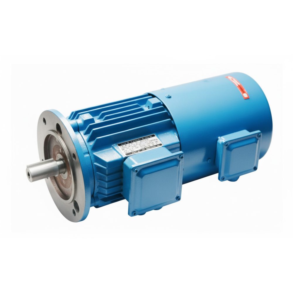
Electric motors convert electrical energy into mechanical motion through electromagnetic interactions between stationary windings and rotating components. Specifically, industrial motors primarily utilize three-phase AC induction designs featuring robust squirrel-cage rotors without brushes, commutators, or wearing electrical contacts. This construction provides exceptional reliability with minimal maintenance requirements compared to DC motors or older wound-rotor designs. The stator houses three-phase windings creating rotating magnetic fields when energized. Subsequently, rotor conductors interact with these fields generating torque rotating the shaft.
Understanding basic motor construction guides effective electric motor maintenance strategies. Critical components requiring attention include stator windings vulnerable to insulation breakdown from thermal, electrical, or environmental stress. Additionally, bearings support rotating assemblies and represent the most common failure point requiring regular lubrication and periodic replacement. Shaft integrity proves essential maintaining concentricity and transmitting torque to driven loads. Furthermore, motor frames provide structural support, mounting points, and heat dissipation paths. Cooling systems including fans, air passages, and external cooling provisions prevent overheating degrading insulation and accelerating component wear.
Common Motor Types and Maintenance Considerations
Different motor types present unique maintenance requirements and failure characteristics. Standard efficiency motors meeting basic performance requirements prove economical initially but consume more energy over service life. In contrast, premium efficiency motors (IE3) and super-premium efficiency motors (IE4) incorporate superior materials, optimized designs, and tighter manufacturing tolerances reducing losses. These motors justify higher initial costs through energy savings and often exhibit improved reliability. However, they may require more careful maintenance protecting premium components.
Variable frequency drive (VFD) compatible motors feature enhanced insulation systems withstanding voltage stresses from VFD operation. Importantly, standard motors operated on VFDs may experience premature insulation failures without these protective features. Brake motors integrate electromagnetic brakes requiring periodic inspection and adjustment maintaining proper function. Moreover, severe duty motors for demanding applications incorporate reinforced construction, premium bearings, and enhanced cooling justifying their cost through extended life in harsh conditions. Each motor type demands tailored electric motor maintenance approaches addressing specific vulnerabilities and operational requirements.
Motor Nameplate Information and Documentation
Motor nameplates provide essential information guiding proper electric motor maintenance and troubleshooting. Critical data includes voltage and frequency requirements, full load amperage indicating normal current draw, power output in kilowatts or horsepower, speed in RPM, service factor indicating overload capacity, duty cycle classification, insulation class defining temperature limits, and frame size determining mounting dimensions. Therefore, recording this information in maintenance management systems ensures proper parts procurement and enables trend analysis across similar motors.
Beyond nameplate data, maintaining comprehensive motor documentation proves invaluable. Original installation records document mounting details, alignment specifications, and commissioning test results. Additionally, maintenance histories track inspection findings, repairs performed, component replacements, and failure modes experienced. Operating parameters including run hours, cycle counts, and load factors enable condition-based maintenance scheduling. Furthermore, thermal imaging baseline data, vibration signatures, and electrical test results provide comparison standards detecting developing problems. Digital documentation systems facilitate data retrieval supporting informed maintenance decisions.
Preventive Maintenance Schedules and Inspection Procedures
Daily and Weekly Motor Inspection Tasks
Daily visual inspections by operators represent the first line of defense in electric motor maintenance programs. These brief examinations identify obvious problems before they cause failures or safety hazards. Specifically, inspection checklists should verify motors operate at normal sound levels without unusual noises indicating bearing wear or mechanical problems. Check for abnormal vibration levels detectable by touch or observation. Additionally, verify cooling airflow remains unobstructed with clean ventilation openings. Observe operating temperatures ensuring motors run cool enough to hold hand comfortably on frame surfaces. Finally, listen for bearing noise including grinding, squealing, or rumbling sounds indicating lubrication problems or bearing damage.
Weekly inspections by maintenance personnel expand examination scope beyond basic operator checks. First, verify all mounting bolts remain tight preventing movement causing misalignment or structural damage. Next, inspect terminal box connections ensuring tightness preventing arcing and overheating. Check motor surroundings removing dust, debris, or obstructions affecting cooling. Moreover, examine flexible couplings or belt drives for wear, alignment, or tension problems. Test rotation direction verifying proper operation after any electrical work. Finally, document all findings systematically tracking trends indicating developing problems requiring deeper investigation.
Monthly Preventive Maintenance Activities
Monthly electric motor maintenance tasks performed by qualified technicians provide thorough component examination and essential servicing. First, measure motor current on all three phases comparing values against nameplate ratings. Significant deviations indicate electrical problems, mechanical overloads, or voltage imbalances requiring investigation. Subsequently, record operating temperatures using infrared thermometers or thermal imaging cameras establishing trend data. Hot spots indicate cooling problems, electrical issues, or bearing failures developing.
Clean motor external surfaces removing accumulated dirt, oil, or contamination impairing heat dissipation. Use compressed air, vacuum cleaners, or soft brushes removing loose contamination. Alternatively, stubborn deposits may require solvent wiping or specialized cleaning compounds. Never use high-pressure water on standard motors as moisture infiltration causes insulation damage. Inspect ventilation passages ensuring unobstructed airflow through cooling systems. Additionally, check drain holes in motor bases ensuring moisture can escape preventing corrosion. Lubricate motors with regreasable bearings following manufacturer specifications regarding lubricant type, quantity, and interval. Over-lubrication proves as problematic as insufficient lubrication causing seal damage and increased temperatures.
Quarterly and Semi-Annual Maintenance Procedures
Quarterly electric motor maintenance includes detailed mechanical and electrical assessments beyond routine monthly activities. Perform vibration analysis using portable analyzers measuring overall vibration levels and frequency spectra. Compare readings against baseline data and industry standards. Increasing vibration indicates bearing wear, rotor imbalance, misalignment, or looseness requiring corrective action. Subsequently, conduct thermographic surveys examining motors under load identifying hot spots invisible during visual inspection. Temperature differentials between phases, bearings hotter than normal, or frame hot spots indicate problems demanding attention.
Test insulation resistance using megohm meters applying DC voltage between windings and ground measuring resistance. Declining values indicate insulation deterioration from moisture, contamination, or aging requiring investigation. Industry standards recommend minimum 1 megohm plus 1 megohm per 1000 volts rating. Values below this threshold warrant concern though motors often operate satisfactorily with lower readings. However, trending proves more valuable than single measurements. Rapidly declining insulation resistance suggests accelerating deterioration requiring prompt action.
Inspect mechanical couplings, belts, or gear drives connecting motors to loads. Check alignment using precision instruments. Misalignment causes premature bearing failure, shaft damage, and excessive vibration. Verify belt tension falls within manufacturer specifications. Loose belts slip reducing efficiency while overtight belts overload bearings. Replace worn belts before failure occurs. Furthermore, check coupling condition for wear, cracks, or deterioration. Document all measurements establishing equipment history supporting predictive maintenance decisions.
Annual Comprehensive Motor Inspections
Annual comprehensive inspections provide thorough motor evaluation determining overall condition and remaining service life. These detailed examinations often coincide with scheduled plant shutdowns enabling extensive testing and servicing impractical during normal operations. Remove motors from service allowing complete inspection without operational constraints. Conduct comprehensive electrical testing including insulation resistance, polarization index, and winding resistance measurements. These tests reveal insulation condition more thoroughly than basic megohm testing.
Disassemble motors for internal inspection when warranted by age, duty cycle, or concerning test results. Examine stator windings for contamination, moisture, cracking, or discoloration indicating overheating. Inspect rotor bars for cracks or looseness. Additionally, check bearing condition through visual examination and feel testing. Bearings exhibiting roughness, pitting, or excessive wear require replacement. Measure shaft runout and straightness ensuring specifications remain acceptable. Inspect cooling fans for damage, security, and proper clearances.
Clean motor internals thoroughly removing accumulated contamination. Dry windings completely if moisture presence detected. Apply protective coatings when appropriate for motor operating environment. Moisture-resistant varnishes protect windings in high-humidity applications. Similarly, special coatings resist chemical attack in aggressive atmospheres. Replace bearings according to service life recommendations even if current condition appears adequate. Bearings approaching design life may fail suddenly without warning. Reassemble motors carefully following proper procedures. Finally, conduct post-maintenance testing verifying proper operation before returning to service. Document all work performed, parts replaced, and test results maintaining comprehensive maintenance records.
Critical Electric Motor Maintenance Tasks
Bearing Lubrication and Replacement
Understanding Bearing Maintenance Requirements
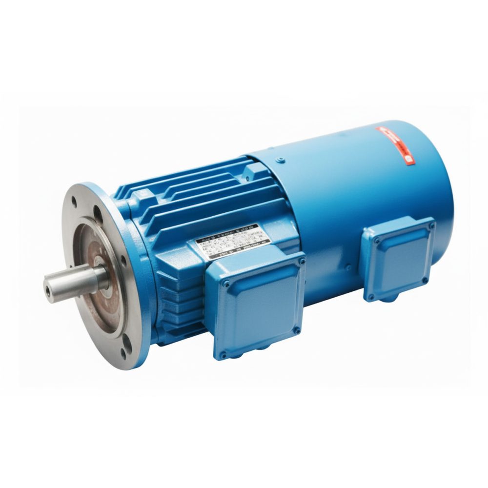
Bearing maintenance represents the most critical routine electric motor maintenance activity directly impacting service life and reliability. Motors with sealed bearings require no lubrication throughout bearing design life typically 20,000-40,000 hours depending on motor size, speed, and operating conditions. In contrast, these motors need bearing replacement when design life expires or bearing damage occurs. Larger motors incorporate regreasable bearings requiring periodic lubrication following manufacturer schedules.
Proper Lubrication Intervals and Techniques
Proper lubrication intervals depend on motor speed, bearing size, orientation, operating temperature, and duty cycle. Generally speaking, motors operating continuously at normal temperatures require lubrication every 2000-4000 hours. Furthermore, high-speed motors, elevated temperatures, or contaminated environments demand more frequent attention. Under-lubrication causes accelerated wear and premature failure. Conversely, over-lubrication equally problematic increases operating temperature, damages seals, and may interfere with motor electrical components if excess grease enters stator area.
Selecting and Applying the Right Lubricants
Use only manufacturer-specified lubricants or approved equivalents. Importantly, mixing incompatible greases causes breakdown providing inadequate protection. Common industrial motor bearings utilize NLGI Grade 2 lithium complex or polyurea greases with appropriate temperature ratings. Moreover, apply correct quantities avoiding both starvation and excess. Many manufacturers provide specific regreasing amounts based on bearing size. Purge old lubricant when possible by operating motor after fresh grease application allowing excess to expel through drain ports. This practice removes contaminated lubricant and ensures fresh material reaches bearing surfaces.
Bearing Replacement Procedures
Replace bearings when wear exceeds acceptable limits, contamination occurs, or design life expires. Specifically, bearing replacement requires proper procedures preventing damage during installation. Press bearings using appropriate fixtures applying force to correct races. Never apply installation force through rolling elements causing immediate damage. Instead, heat bearings uniformly before installation expanding inner races for easier mounting. Ensure shaft and housing bore cleanliness preventing contamination during assembly. Set proper shaft clearances and preload per specifications. Improper installation causes rapid failure negating new bearing investment.
Motor Alignment and Vibration Control
Proper alignment between motors and driven equipment proves essential for reliable operation and extended bearing life. Misalignment creates excessive radial and axial bearing loads causing premature failure. Additionally, it generates vibration reducing component life, increases energy consumption, and may cause shaft fatigue or coupling damage. Two basic alignment types require attention: angular misalignment where shaft centerlines meet at an angle, and parallel misalignment where shafts remain parallel but offset.
Precision alignment requires appropriate instruments and procedures. Dial indicator methods provide adequate accuracy for less critical applications. However, laser alignment systems offer superior precision and efficiency justifying investment for facilities maintaining numerous motors. Alignment should occur with equipment at operating temperature as thermal expansion affects positions. Soft foot conditions where motor mounting surfaces don’t sit flat on bases must be corrected before alignment as they prevent achieving proper results.
Vibration monitoring provides valuable electric motor maintenance insights enabling early problem detection. Establish baseline vibration measurements on new or refurbished motors creating comparison standards. Subsequently, conduct periodic measurements trending data over time. Increasing vibration levels indicate developing problems including bearing wear, rotor imbalance, looseness, misalignment, or resonance conditions. Furthermore, vibration analysis examining frequency components identifies specific fault types. For example, bearing defects generate characteristic frequencies related to bearing geometry enabling precise diagnosis.
Address vibration problems promptly preventing accelerated damage. Solutions depend on root causes identified through analysis. Bearing replacement corrects bearing-related vibration. Balancing addresses rotor imbalance. Similarly, alignment correction eliminates misalignment vibration. Tightening loose components addresses looseness. Sometimes multiple corrective actions prove necessary addressing complex problems. Professional vibration analysis services provide expertise for difficult cases exceeding in-house capabilities.
Electrical Testing and Insulation Monitoring
Electrical testing provides critical information about motor winding condition enabling predictive maintenance decisions. Insulation resistance testing using megohm meters represents the most basic electrical test. Apply DC voltage between windings and ground measuring resistance. Perform tests with motors at consistent temperature as temperature significantly affects readings. Convert measurements to standard temperature (typically 40°C) using correction factors enabling valid comparisons. Therefore, record all readings establishing trend data. Gradually declining values indicate deteriorating insulation requiring investigation.
Polarization index testing expands basic insulation resistance testing providing additional information. Measure insulation resistance after 1 minute and again after 10 minutes of applied voltage. Calculate polarization index by dividing 10-minute reading by 1-minute reading. Healthy insulation exhibits PI values above 2.0 as moisture and contamination redistribute during testing. Conversely, values below 2.0 suggest contamination, moisture, or deteriorated insulation. Combined with insulation resistance trending, PI testing provides comprehensive assessment of insulation condition.
Winding resistance testing measures DC resistance of each motor phase. Compare measurements between phases and against baseline values. Significant differences between phases indicate problems including shorted turns, poor connections, or damaged conductors. Increasing resistance over time suggests connection deterioration or conductor damage. Alternatively, decreasing resistance may indicate shorted turns. Temperature affects resistance significantly so convert measurements to standard temperature enabling valid comparisons. Record all values maintaining comprehensive motor history.
Current signature analysis examines motor current waveforms identifying electrical and mechanical problems. Specialized instruments analyze current patterns detecting rotor bar cracks, air gap irregularities, electrical unbalance, and various mechanical faults. This advanced technique provides diagnostic capabilities beyond basic electrical testing. Therefore, consider implementing current signature analysis for critical motors where unexpected failures cause significant business impact. Periodic testing establishes normal signatures enabling comparison detecting developing problems.
Motor Cleaning and Environmental Protection
Maintaining motor cleanliness proves essential for proper cooling, preventing contamination-related failures, and extending service life. Accumulated dirt, dust, oil, or debris on motor surfaces insulates frames preventing heat dissipation. Consequently, this causes elevated operating temperatures accelerating insulation aging and reducing component life. Cooling air passages blocked by contamination reduce airflow exacerbating cooling problems. Additionally, external contamination may infiltrate motors through ventilation openings causing internal damage.
Cleaning procedures depend on motor enclosure type and contamination present. Open motors require careful cleaning avoiding moisture introduction into electrical areas. Use compressed air, vacuum cleaners, or soft brushes removing loose contamination. Stubborn deposits may require solvent wiping or specialized cleaning compounds. Totally enclosed motors allow more aggressive external cleaning but still require caution around terminal boxes and shaft seals. Never use high-pressure water jets on standard motors as moisture penetration causes insulation damage.
Internal motor cleaning during disassembly requires thorough contamination removal and complete drying before reassembly. Use appropriate solvents compatible with insulation materials dissolving oil, grease, or other deposits. Vacuum loose debris carefully avoiding damage to windings. Bake motors if necessary removing all moisture before energizing. Apply protective coatings when appropriate for motor operating environment. Moisture-resistant varnishes protect windings in high-humidity applications. Similarly, special coatings resist chemical attack in aggressive atmospheres.
Environmental protection measures prevent contamination and moisture infiltration extending time between required cleanings. Properly seal conduit entries preventing moisture or contamination ingress through electrical connections. Maintain gasket integrity around terminal boxes and removable covers. Install shaft slingers or deflectors preventing contamination entry around shafts. Moreover, consider installing filters on cooling air intakes in extremely contaminated environments. Ensure proper motor selection for environment with appropriate enclosure types and protective features. TEFC motors suit most industrial environments while totally enclosed air-over designs or explosion-proof construction address special requirements.
Troubleshooting Common Electric Motor Problems
Identifying Motor Overheating Causes
Motor overheating represents one of the most common problems reducing insulation life and component reliability. Every 10°C temperature increase above rated values roughly halves insulation service life. Therefore, identifying root causes enables implementing effective corrective actions. Common overheating causes include excessive loading beyond nameplate rating, voltage unbalance or incorrect voltage, restricted cooling from blocked ventilation, high ambient temperature, bearing problems increasing friction losses, rotor problems including broken bars, and frequent starting in applications exceeding duty cycle ratings.
Diagnosis begins with measuring motor current comparing values to nameplate full load amperage. Current exceeding FLA indicates overloading requiring load reduction or motor replacement with higher capacity. Meanwhile, voltage measurements at motor terminals identify supply problems. Voltage unbalance exceeding 1-2% causes significant temperature rise and must be corrected. Verify that supply voltage falls within ±10% of nameplate rating. Check that cooling system function ensuring unobstructed airflow through ventilation passages and proper fan operation.
Thermal imaging provides powerful diagnostic capabilities identifying hot spots and temperature distribution patterns. Compare temperatures between phases. Significant differences indicate electrical problems. Bearings running substantially hotter than normal suggest lubrication problems or bearing damage. Similarly, frame temperature distribution reveals cooling problems. Hot spots at winding areas may indicate localized insulation damage or turn-to-turn shorts.
Solutions depend on identified root causes. Reduce loading, upsize motor, or improve driven equipment efficiency addressing overload problems. Correct electrical supply issues including voltage unbalance and improper voltage. Clean cooling passages and ensure proper ventilation addressing cooling problems. Repair or replace defective components including bearings or damaged rotors. Limit starting frequency or use special duty motors for demanding start-stop cycles. Additionally, consider upgrading to premium efficiency motors running cooler than standard designs at equivalent loads.
Diagnosing Bearing Failures
Bearing failures represent the leading cause of motor breakdowns accounting for 40-50% of premature motor failures. Understanding failure modes and root causes enables implementing preventive measures. Specifically, common bearing failure types include wear from inadequate lubrication, contamination from dirt or moisture entering bearing areas, overloading from excessive belt tension or misalignment, electrical erosion from bearing currents in VFD applications, corrosion from moisture or chemical exposure, and fatigue from exceeding design life.
Early detection proves critical preventing collateral damage. Warning signs include increasing vibration levels, rising bearing temperatures, unusual noise including grinding or squealing, and visible contamination around bearing seals. Therefore, regular condition monitoring identifies these symptoms enabling planned bearing replacement during scheduled maintenance rather than responding to unexpected failures.
Failed bearing inspection reveals root causes guiding corrective actions. Wear patterns suggest lubrication problems. Pitting indicates contamination. Similarly, smearing or cage damage suggests overloading. Fluting patterns reveal electrical erosion from bearing currents. Rust indicates moisture exposure. This forensic analysis prevents recurrence by addressing fundamental problems rather than simply replacing bearings.
Corrective measures address identified root causes. Improve lubrication practices including proper intervals, correct quantities, and appropriate lubricant types. Enhance sealing preventing contamination ingress. Correct alignment and belt tension eliminating overloading. Install insulated bearings or shaft grounding systems addressing bearing current problems in VFD applications. Moreover, improve moisture protection through better sealing or environmental controls. Replace bearings proactively before design life expires preventing unexpected failures.
Electrical Problems and Solutions
Identifying Common Electrical Issues
Electrical problems manifest in various symptoms including failure to start, tripping protective devices, excessive current draw, overheating, and poor performance. Accordingly, systematic diagnosis identifies specific faults enabling targeted repairs. Generally, problems divide into supply issues external to motors and internal motor faults requiring different corrective approaches.
Diagnosing Supply Problems
Supply problems include incorrect voltage, voltage unbalance, phase loss, frequency variation, and poor power quality. Therefore, voltage measurements at motor terminals identify these conditions. Incorrect voltage requires correction at distribution system. Additionally, voltage unbalance exceeding 2% demands investigation of supply imbalance, unequal loading, or poor connections. Phase loss protection prevents motor operation with missing phase preventing damage. Frequency variation outside normal range affects motor performance and must be addressed at source.
Identifying Internal Motor Faults
Internal motor faults include winding failures from insulation breakdown, shorted turns, open circuits, and rotor problems. Consequently, insulation resistance testing identifies ground faults. Similarly, winding resistance measurements detect opens or shorts. Furthermore, current signature analysis reveals rotor bar problems. Careful diagnosis determines whether repair or replacement proves most economical considering motor age, failure severity, and repair costs compared to new motor prices.
Making Repair vs Replacement Decisions
Motor repair decisions balance repair costs against replacement costs and efficiency considerations. For instance, simple problems including bearing replacement, terminal connection repair, or cleaning and testing prove straightforward economically. However, major repairs including rewinds require careful evaluation. Factor in motor age, efficiency considerations (modern motors often substantially more efficient than older units), expected remaining service life after repair, and potential reliability improvements from new equipment. Consult reputable motor repair shops providing detailed cost estimates and performance guarantees.
Vibration Analysis and Correction
Excessive vibration reduces motor and driven equipment life, increases energy consumption, generates noise, and may indicate developing failures. Understanding vibration sources enables effective correction. Common causes include unbalanced rotors, misalignment, bearing wear or damage, mechanical looseness, resonance conditions, and driven equipment problems transmitted through connections.
Basic vibration screening uses portable vibration meters measuring overall vibration levels. Compare readings against industry standards. New motors typically exhibit vibration below 0.1 inches/second. Values exceeding 0.3 inches/second warrant investigation. Increasing trends even within acceptable absolute levels indicate developing problems requiring attention.
Detailed vibration analysis examines frequency components identifying specific fault types. Each problem generates characteristic frequency patterns. Imbalance produces vibration at running speed (1X RPM). Misalignment creates 1X and 2X running speed components with significant axial vibration. Similarly, bearing defects generate frequencies related to bearing geometry. Looseness produces multiple harmonics. Professional analysts interpret spectra precisely identifying faults.
Corrective actions address identified root causes. Balance rotors correcting mass distribution. Subsequently, realign equipment eliminating misalignment. Replace worn bearings. Tighten loose components. Modify resonant structures changing natural frequencies. Sometimes multiple corrections prove necessary addressing complex problems. Finally, verify corrections through post-repair vibration measurements confirming problem resolution.
Energy Efficiency Through Proper Maintenance
Maintaining Peak Motor Efficiency
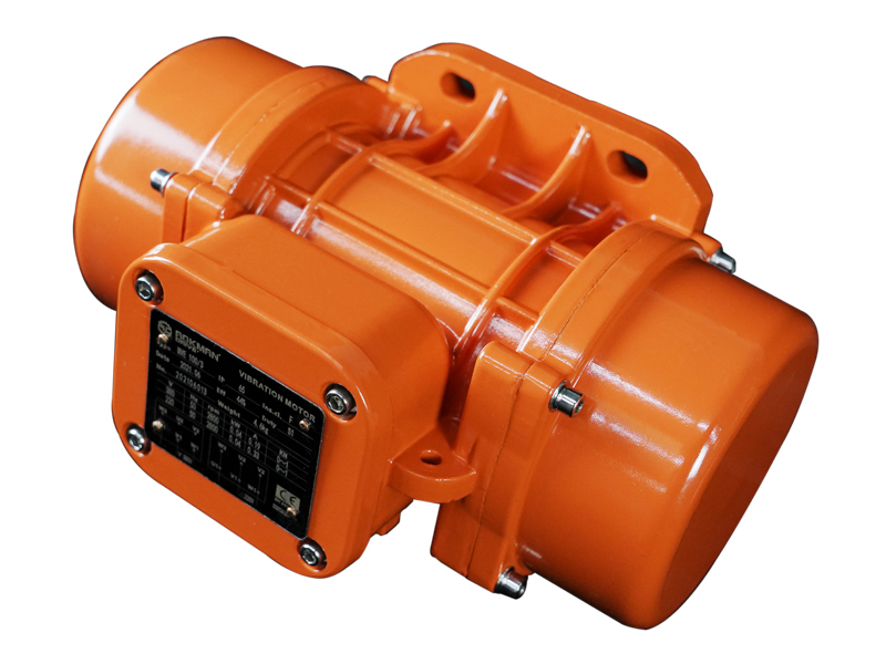
Motor efficiency directly impacts operating costs given that motors typically consume electricity worth 10-50 times purchase price over service life. Proper electric motor maintenance preserves efficiency preventing gradual degradation from neglect. Clean motors run cooler and more efficiently than contaminated units. Proper lubrication reduces friction losses. Similarly, correct alignment eliminates efficiency penalties from misalignment. Repairing voltage unbalance, eliminating electrical problems, and maintaining proper cooling all preserve design efficiency.
Monitor motor operating conditions periodically. Measure input power, voltage, current, and power factor comparing against baseline values. Efficiency degradation reveals itself through increasing input power for constant output. Thermal inefficiency manifests as elevated temperatures. Mechanical inefficiency appears as increased vibration or noise. Therefore, regular monitoring enables early detection addressing problems before significant efficiency deterioration occurs.
Consider motor replacement rather than repair for failed older motors. Modern premium efficiency motors often recover incremental cost through energy savings within 2-4 years. Factor in repair costs, expected remaining life after repair, and energy cost differences. Many utilities offer rebates for high-efficiency motor purchases improving economics. Replacement proves especially attractive for motors operating many hours annually where energy costs dominate lifecycle expenses.
Optimize motor loading for best efficiency. Motors typically achieve peak efficiency at 75-90% of rated load. Operation significantly below this range reduces efficiency though efficiency loss proves less severe than once believed. Avoid oversized motors operating constantly at light loads. Right-size motors for actual applications balancing adequate capacity against efficiency optimization. Furthermore, variable frequency drives enable speed reduction for variable load applications dramatically improving system efficiency compared to throttling or mechanical control methods.
Power Quality and Motor Performance
Power quality problems including voltage unbalance, harmonics, voltage sags, and transients negatively impact motor performance, efficiency, and reliability. Understanding these problems enables implementing protective measures. Voltage unbalance forces motors to draw unbalanced currents generating excessive heating reducing insulation life. Even 2-3% voltage unbalance significantly degrades performance and service life. Harmonics from VFDs and other nonlinear loads cause additional heating and losses.
Monitor power quality periodically using appropriate instruments. Voltage unbalance should remain below 1% ideally though motors tolerate up to 2% without severe degradation. Beyond this level investigate supply problems and implement correction through phase balancing or installing voltage balancing equipment. Harmonic distortion should stay below 5% total harmonic distortion (THD). Higher levels may require harmonic filters protecting sensitive equipment.
VFD applications introduce special considerations. While VFDs dramatically improve system efficiency through speed control, they generate harmonics, voltage spikes, and common-mode currents potentially damaging standard motors. Use inverter-duty motors featuring enhanced insulation systems withstanding VFD stresses. Install line reactors or harmonic filters reducing harmonic content. Proper VFD programming minimizes motor stress while maximizing efficiency. Moreover, ensure adequate cable sizing and proper grounding preventing electrical problems.
Protection devices prevent damage from power quality problems and faults. Motor protection relays provide sophisticated protection beyond simple thermal overloads. These devices monitor voltage, current, power factor, and other parameters detecting problems before damage occurs. Ground fault detection prevents insulation breakdown fires. Phase loss protection stops motors when supply phases fail. Setting protection properly balances preventing nuisance trips against providing adequate protection. Coordination with upstream protective devices ensures proper system operation.
Documentation and Record Keeping for Motor Maintenance
Establishing Comprehensive Maintenance Records
Effective electric motor maintenance programs depend on thorough documentation tracking equipment history, maintenance activities, and performance trends. Comprehensive records support informed decision-making, identify recurring problems, demonstrate regulatory compliance, and provide valuable information during troubleshooting. Minimum essential records include motor inventory with nameplate data and location information, maintenance schedules with planned activities and completion tracking, work orders documenting all maintenance performed, and test results from electrical testing, vibration analysis, and thermal surveys.
Computerized maintenance management systems (CMMS) provide powerful tools organizing motor maintenance information. These systems enable scheduling preventive maintenance automatically, generating work orders, tracking completion, maintaining equipment histories, analyzing failure patterns, managing spare parts inventory, and reporting maintenance metrics. Implementation requires initial data entry investment but delivers substantial value through improved maintenance efficiency and reliability insights.
Beyond basic maintenance records, maintain technical documentation including original equipment manuals, wiring diagrams, and installation specifications. Modification records track changes from original configurations. Similarly, vendor information including contact details and parts sources proves valuable during repairs. Failure analysis reports document root cause investigations and corrective actions preventing recurrence. Organize documentation logically enabling quick access during maintenance activities or troubleshooting emergencies.
Key Performance Indicators for Motor Maintenance
Measuring motor maintenance program effectiveness requires defining and tracking relevant performance indicators. Common metrics include mean time between failures (MTBF) indicating overall reliability, planned maintenance percentage showing proactive versus reactive balance, maintenance cost per motor tracking efficiency, motor failures per 1000 operating hours enabling benchmarking, and energy consumption trends revealing efficiency degradation. Establish baselines and targets for each metric. Therefore, regular review identifies improvement opportunities.
Reliability metrics including MTBF and failure rates provide overall program effectiveness measures. Increasing MTBF indicates improving reliability from better maintenance. Conversely, rising failure rates suggest inadequate maintenance or equipment approaching end-of-life. Break down failures by cause identifying systematic problems. Bearing failures, winding failures, and other categories reveal specific weaknesses guiding program adjustments.
Cost metrics balance maintenance investment against reliability benefits. Low maintenance costs may indicate inadequate investment risking failures and downtime. Excessive costs suggest inefficient practices or over-maintenance. Benchmark against industry standards and similar facilities. Track cost per operating hour normalizing for different utilization levels. Monitor emergency repair costs separately as high emergency expense indicates insufficient preventive maintenance.
Energy monitoring identifies efficiency degradation from poor maintenance or provides baseline data justifying motor replacements. Measure power consumption periodically comparing against baseline values. Significant increases without corresponding load changes indicate problems requiring investigation. Document energy savings from efficiency improvements quantifying maintenance program value beyond reliability benefits.
Specialized Motor Maintenance Considerations
VFD Motor Maintenance Requirements
Motors operated on variable frequency drives require additional electric motor maintenance considerations beyond standard applications. VFD output voltage waveforms contain high-frequency switching components creating voltage stresses on motor insulation. Common-mode currents flow through bearings potentially causing electrical erosion damage. Additionally, heating from harmonic currents may exceed standard motor cooling capabilities at reduced speeds. These factors demand special attention preventing premature failures.
Use inverter-duty motors specifically designed for VFD operation when possible. These motors feature reinforced insulation systems withstanding voltage stresses, improved bearing systems accommodating or insulating against bearing currents, and enhanced cooling maintaining adequate heat dissipation across operating speed range. When applying standard motors to VFDs, use output filters reducing voltage stress or derate motors compensating for additional heating.
Inspect VFD motor bearings carefully for fluting damage characteristic of bearing current erosion. This distinctive damage pattern consists of fine grooves in bearing raceways appearing as frosted or etched surfaces. Once initiated, damage progresses rapidly leading to premature failure. Therefore, install shaft grounding systems or insulated bearings preventing bearing current flow in motors experiencing this problem. Monitor bearing condition frequently enabling early detection.
VFD maintenance extends beyond motors to drive systems themselves. Clean cooling fins and check fan operation maintaining proper drive operating temperature. Verify control parameters remain properly set after updates or modifications. Monitor drive output voltage quality using oscilloscope or VFD diagnostic features. Test insulated gate bipolar transistors (IGBTs) and other power components according to manufacturer recommendations. Finally, maintain detailed records of parameter settings enabling quick restoration after failures or replacements.
Explosion-Proof and Hazardous Location Motors
Motors installed in classified hazardous locations require special electric motor maintenance procedures ensuring continued protection integrity. These motors feature heavy-duty enclosures containing any internal ignition source preventing external atmosphere ignition. Maintenance procedures must preserve protective features. Opening motors without proper precautions violates safety requirements and creates severe hazard risks.
Verify power disconnection and lockout before opening hazardous location motors. Confirm atmosphere testing proves non-hazardous before conducting maintenance in classified areas. Never open motors while energized or in potentially explosive atmospheres. Inspect enclosure gaskets and flanges during maintenance ensuring proper sealing. Replace damaged gaskets immediately. Flame paths between enclosure joints require specific gap tolerances. Never alter enclosures or modify mounting hardware potentially compromising protection.
Documentation proves especially critical for hazardous location motors. Maintain records verifying proper equipment selection for area classification. Track enclosure inspection findings and gasket replacements. Document all modifications including wiring changes, component replacements, or mounting alterations. Modifications require engineering evaluation ensuring continued compliance with area classification requirements. Unauthorized modifications void certifications and create serious liability exposures.
Training personnel maintaining hazardous location equipment proves essential. Technicians need understanding of area classification systems, equipment protection methods, and proper maintenance procedures preserving safety. Maintenance errors potentially catastrophic in explosive atmospheres demand qualified, trained personnel. Regular refresher training maintains competency as equipment and requirements evolve.
Vertical Motor Special Requirements
Vertical motors supporting axial loads from driven equipment and motor rotor weight require special maintenance attention. Thrust bearings carry axial loads in addition to radial loads borne by radial bearings. Thrust bearing condition proves critical as failure allows rotor to move axially potentially causing catastrophic damage. Therefore, monitor thrust bearing condition carefully through vibration analysis, temperature monitoring, and periodic inspection.
Measure axial clearances during maintenance verifying thrust bearing adjustment remains within specifications. Excessive clearance indicates wear requiring adjustment or bearing replacement. Conversely, insufficient clearance causes overloading and premature failure. Thrust bearing lubrication requires particular attention ensuring adequate lubricant reaches bearing surfaces. Vertical motors may require different lubricants or lubrication procedures compared to horizontal motors given different loading and orientation.
Shaft alignment on vertical motors demands precision given axial load considerations. Verify coupling concentricity and face alignment within tight tolerances. Misalignment creates alternating axial forces accelerating thrust bearing wear. Check shaft straightness and runout ensuring specifications remain acceptable. Bent shafts cause unacceptable loading patterns. Support shaft weight properly during disassembly preventing bending from inadequate support.
Sealing proves especially critical on vertical motors preventing lubricant loss or contamination entry. Inspect seals carefully during maintenance. Replace damaged or aged seals proactively. Verify proper seal orientation and installation preventing premature failure. Additionally, consider sealed bearing designs eliminating relubrication requirements and sealing concerns for smaller vertical motors where this option proves feasible.
Cost-Effective Motor Maintenance Strategies
Predictive vs Preventive Maintenance Approaches
Traditional preventive maintenance follows time-based schedules performing maintenance at fixed intervals regardless of actual equipment condition. This approach proves simple to implement and ensures motors receive regular attention. However, time-based maintenance may result in unnecessary work on motors in good condition or miss problems developing between scheduled intervals. In contrast, predictive maintenance uses condition monitoring determining actual motor condition and performing maintenance only when indicators suggest it’s needed.
Predictive techniques include vibration analysis monitoring bearing condition, thermal imaging detecting overheating, insulation resistance testing tracking winding condition, and oil analysis evaluating lubricant condition in special applications. These technologies enable condition-based maintenance scheduling optimizing resources. Predictive approaches require initial investment in equipment and training but deliver excellent returns through optimized maintenance timing, prevented failures, and reduced unnecessary maintenance.
Optimal strategies combine preventive and predictive elements. Base-level preventive maintenance including cleaning, lubrication, and basic inspections occur at regular intervals. Additionally, predictive monitoring targets critical motors where failures cause significant impact or on motors exhibiting concerning trends. This hybrid approach balances program simplicity and effectiveness with sophisticated monitoring where justified by business value.
Balancing In-House and Contracted Services
Most facilities perform routine electric motor maintenance using in-house personnel while contracting specialized services beyond internal capabilities. This approach balances cost-effectiveness with access to expertise and equipment. Routine tasks including cleaning, lubrication, basic inspections, and simple repairs suit in-house execution with trained technicians. In contrast, contract specialized services including motor rewinding, dynamic balancing, precision machining, and advanced diagnostic testing.
Evaluate make-versus-buy decisions considering workload volume, required expertise, equipment investment, and quality requirements. Facilities with many motors justify investing in vibration analyzers, thermal cameras, and other diagnostic equipment. Conversely, smaller facilities find contracting periodic surveys more economical. Motor rewinding decisions balance repair shop capabilities, turnaround time requirements, and economics. Large facilities may justify in-house rewind capabilities while smaller operations contract this work.
Establish relationships with reputable motor repair shops and service providers. Quality varies significantly between providers affecting repair reliability and value. Check references, visit facilities, and review capabilities before committing significant work. Verify repair shops maintain proper equipment, employ trained technicians, and follow industry best practices. Request detailed proposals and warranties ensuring clear understanding of work scope and guarantees.
Maintain clear communications between internal maintenance staff and external service providers. Provide complete information about motor history, operating conditions, and failure symptoms enabling accurate diagnosis. Review completed work thoroughly before acceptance verifying quality and completeness. Finally, integrate external service work into maintenance records maintaining comprehensive equipment histories.
Spare Parts Strategy and Inventory Management
Effective spare parts programs balance carrying costs against downtime risks from parts unavailability. Critical spares for motor maintenance typically include bearings for common frame sizes, replacement motors for critical applications where failures cause significant impact, common electrical components including contactors and overloads, and maintenance supplies including lubricants, cleaning materials, and test equipment consumables. Avoid excessive inventory tying up capital in slow-moving stock.
Analyze motor population identifying common frame sizes, types, and critical applications guiding spare parts decisions. Stock bearings for most common sizes enabling rapid replacement. Maintain spare motors for critical applications where extended downtime proves unacceptable and repair/replacement lead times exceed tolerance. Establish vendor relationships guaranteeing rapid delivery for items too expensive stocking. Some organizations pool spare parts with nearby facilities sharing costs while improving availability.
Implement inventory management systems tracking parts quantities, locations, costs, and usage. Set appropriate reorder points preventing stockouts while avoiding excessive inventory. Conduct regular audits verifying physical inventory matches records. Identify obsolete items for disposal freeing storage space and capital. Review usage patterns periodically adjusting stocking levels based on actual consumption.
Consider extending warranties, service contracts, or stocking arrangements with motor suppliers. These arrangements provide parts availability guarantees, potential cost savings, and reduced inventory investment. Evaluate costs versus benefits determining optimal approach for your situation. Large facilities may justify significant inventory while smaller operations benefit from external support arrangements.
Frequently Asked Questions
How often should electric motors be lubricated?
Lubrication frequency depends on motor size, speed, duty cycle, and environment. Small motors with sealed bearings need no lubrication throughout bearing life. In contrast, larger motors with regreasable bearings typically require lubrication every 2000-4000 hours under normal conditions. Furthermore, high-speed motors, high temperatures, or contaminated environments demand more frequent lubrication. Always follow manufacturer recommendations for specific motors. Over-lubrication causes problems equal to under-lubrication.
What causes most electric motor failures?
Bearing failures account for 40-50% of premature motor failures resulting from inadequate lubrication, contamination, or overloading. Stator winding failures cause 30-40% of failures from insulation breakdown due to overheating, moisture, contamination, or age. Additionally, rotor problems including broken bars account for 10% of failures. External factors including power quality problems, overloading, and environmental conditions contribute to many failures. Proper maintenance significantly reduces failure rates.
How do I know if my motor needs replacement or repair?
Consider motor age, failure severity, repair cost compared to replacement, efficiency considerations, and expected remaining life after repair. Simple repairs including bearing replacement or cleaning prove economical. However, major repairs including rewinds require careful evaluation. Motors over 15-20 years old with major failures often warrant replacement given improved efficiency and reliability of modern motors. Request detailed quotes from reputable repair shops comparing against new motor costs.
Can I test motors without specialized equipment?
Basic testing using multimeters and observation identifies many problems. Measure current comparing to nameplate rating detecting overloads. Check voltage at motor terminals identifying supply problems. Observe operating temperature, noise, and vibration detecting obvious issues. However, specialized equipment including megohm meters, vibration analyzers, and thermal cameras provide valuable diagnostic capabilities justifying investment for facilities with many motors. Consider contracting specialized testing for smaller facilities.
What maintenance records should I keep for motors?
Maintain comprehensive records including motor inventory with nameplate data, maintenance schedules and completion documentation, all repairs and component replacements, test results from electrical and vibration testing, operating parameters including hours and load factors, and failure analysis reports. These records support informed decisions, identify trends, demonstrate compliance, and provide valuable troubleshooting information. Digital CMMS systems facilitate record keeping and analysis.
How can I extend motor life?
Implement comprehensive maintenance programs including regular cleaning, proper lubrication, electrical testing, vibration monitoring, and thermal surveys. Operate motors within ratings avoiding overloading and excessive cycling. Maintain proper alignment and belt tension. Additionally, address power quality problems including voltage unbalance. Protect motors from environmental damage through proper enclosures and installation. Select appropriate motors for applications considering duty requirements and environmental conditions. These practices dramatically extend service life.
Conclusion
Comprehensive electric motor maintenance programs deliver substantial value through improved reliability, extended equipment life, reduced energy consumption, and minimized unplanned downtime. The combination of systematic inspection procedures, condition monitoring technologies, proper lubrication practices, and prompt attention to identified problems significantly reduces failure rates while optimizing maintenance resources. Therefore, organizations should view motor maintenance as strategic investments delivering measurable returns rather than discretionary expenses.
Implementing effective electric motor maintenance requires commitment to systematic procedures, qualified personnel, appropriate tools and equipment, and comprehensive documentation. Whether managing small facilities or large industrial operations, these fundamental principles guide program development ensuring optimal motor reliability and performance. Regular program reviews enable continuous improvement adapting to changing equipment, technology, and operational requirements.
Success depends on organizational commitment from leadership through operations and maintenance personnel. Provide adequate resources including training, equipment, and time enabling proper maintenance execution. Foster communication between operations and maintenance ensuring problems receive prompt attention. Benchmark performance against industry standards identifying improvement opportunities. Through disciplined application of proven maintenance practices, organizations achieve optimal motor reliability supporting manufacturing productivity, operational efficiency, and long-term cost-effectiveness.
Safety Disclaimer: This article provides general guidance only. All electric motor maintenance, testing, repair, and operation must be performed by qualified electrical professionals following applicable safety standards and regulations. Consult certified electricians, comply with OSHA and NFPA requirements, follow manufacturer specifications, and adhere to local electrical codes before proceeding with any maintenance activities.
Technical Specification Disclaimer: Motor specifications, maintenance requirements, and repair procedures vary by manufacturer, model, type, and application. Always refer to manufacturer documentation and consult professional engineers or qualified electricians for equipment-specific requirements. Information presented reflects general industry practices and should be verified for specific circumstances.
Need Expert Electric Motor Maintenance Support? Contact qualified motor service professionals for technical consultation, comprehensive testing programs, preventive maintenance services, and motor repair or replacement recommendations tailored to your specific equipment and operational requirements.